Fuente: http://siber-sonic.com/mac/Vintage/MS1705.html
Originally Web posted Wednesday, 23 April 2008.
Content last modified Wednesday, 23 April 2008 .
External links last verified Wednesday, 23 April 2008.
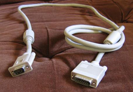
P/N 387-622B (Apple part #922-1877) MS1705 Monitor Cable
This is one of those pages that i really should have put up about 8 years ago. In any event, if anyone besides me still has an Apple Multiple Scan 1705 video monitor (display) and is in need of a cable, the information on this page may prove useful.
Is this cable really that special? Do I need one?
The MS1705 is basically a standard 17″ SVGA or XGA (depending who is asked) CRT display with an Apple logo and a special cable to connect to period Macintosh video circuits. At the time this monitor was a current product, there was some (mis?-)information from Apple[1] implying, but not outright saying, that one absolutely must have this particular magic cable.
Truth is, testing reveals that a standard DE-15M[2] (a.k.a. and not really HD-15M and DB-15HDM) on both ends “VGA” video cable will work just fine when the 1705 is connected to PC-compatible hardware and post-Beige Macs with “VGA-style” video connectors[3]. In fact, while i have found no explicit confirmation, it appears that the MS 1705 supports EDID/DDC.
The same cable, with an adapter to DA-15M (a.k.a. and not really DB-15), works just fine on Beige Macs (at least the 8600/300 i tested explicitly), as long as the sense lines are tugged properly or an adapter like the Griffin Mac PnP is used and set for Plug and Play (or MultiSync 16″/17″, your choice).
In other words, No, one does not need this “special” cable if one has another suitable arrangement as just described.
Those who, for whatever reason, want or need to make their own custom DE-15M to DA-15M cable, or who want confirmation of proper adapter settings (using information on this page + the documentation for the adapter), may wish to continue reading.
Making The Cable
The following information assumes reasonable computer hardware or equivalent electronics knowledge and self-sufficiency… in other words, if you don’t understand a term, you’ll go off and look it up yourself. Anyone who has successfully home-made any sort of electronic data, audio, or similar cable should be all set.
The easiest way to make this custom cable is to start with a standard “VGA” cable, with at least one end with an intact DE-15M connector (usually with blue plastic these days) with at least the pins shown on the left in the drawing above present and connected. It really does not matter what is happening at the other end, as that end will be lopped off and a DA-15M solder cup (or your choice) connector installed in its place, custom wired per the diagram above.
Speaking of the diagram, it contains additional information not relevant to the specific goal of this page: ignore anything in parentheses when making a cable for a MS1705. It is also not necessary to know nor understand the pin designations in the left and right outside columns. As long as the pins are wired per the drawing, with the parenthetic pins left not connected or removed, that should be sufficient. (The extra information may prove useful to those finding this page and needing to make a similar cable for another video monitor, and for the curious.)
For those not familiar with older Macintosh sense codes, these pins (ID 1-3 or sense line 0-2… same thing) were individually or in combination connected to ground or each other on older Mac monitors, in order to tell the main unit (CPU box) what monitor was connected and its resolution abilities. By the mid-1990s Apple had run out of combinations, so multi-scan monitors such as the MS1705 use one or two diodes in either the cable connector (as here) or the monitor to further extend the system. The MS1705 cable needs one diode connected with cathode (marking band) connected to pin 10 of the DA-15M (ID 3), and the anode (no mark) connected to pin 7 (ID 2). ID 1 (pin 4) needs to be connected to circuit common (ground) to complete the correct sensing scheme.
That’s pretty much it. As can be seen in the photo at the top of this page, the original cable had ferrite beads (cylinders, really) near each end for EMI suppression. Without question, the cable needs an overall shield, preferably a good one, connected to the shell of each connector.

While not necessary for this project, and possibly likely to add confusion rather than clarification, folks interested in what Apple has to say regarding display cable wiring may wish to investigate Apple article 6382, Monitor Cables: Pinout Information.

[1]
Apple TIL article 19016, modified 12/5/95.
[2] Anything looking like this in this article is a connector type/model designation. More information is available via Wikipedia and/or your favorite WWW search engine.
[3] The PC-compatible system tested was a Dell XPS series Pentium III running Windows 2000. The newer Mac system tested was a G4 AGP (Sawtooth) with its stock video card.

 World O’ Apple & Macintosh
 The Sonically Pure Pages
This Siber-Sonically Pure Page is  ,
,  , and
, and  Transitional compliant.